Final tally for melt through
August 15, 2017
The final tally for Fukushima melt-throughs?
Post-accident computer simulations indicated that the entire nuclear fuel core, control rods, and core structural materials melted through the reactor (RPV) bottom head for Fukushima unit #1, most through for unit #3, and partially for unit #2. Video imaging recently posted from the submersible robot (i.e. Little Sunfish) exploration of unit #3 pedestal interior has been touted to confirm the computer-simulations.
Let’s look at unit #3. If the entire contents of unit #3’s core barrel liquefied and pooled in the bottom of the RPV, then melted trough the bottom head, there should be at least 210 tons of corium on the floor inside the pedestal! (1) All of this considerable mass and volume should have been visible via the Little Sunfish camera.
But, it wasn’t!
Based on the visual imaging with unit #3, it now seems likely that the bottom heads of none of the units experienced melt through! Any corium (liquefied fuel and supporting materials) that exited the RPVs escaped by another path. What might that path be?
It might be helpful to first look at the specifics with unit #3 to understand why a total melt-through is unlikely. The dimensions of the fuel core for a 2,381 MWth BWR-4 reactor, is 3.7 meters high, and 5.2 meters in diameter. (2) That’s more than 110 cubic meters… nearly 3,900 cubic feet! The density of the fuel bundles and control rods in the core is significant when undamaged, but it shrank into a much smaller volume when everything became liquid… but probably no less than 1,000 ft3. If this volume dropped through the RPV bottom head, all of this considerable debris would be inside the pedestal. When we look at the still images and video from the “Little Sunfish”, it appears to be much less! (3) A few hundred cubic feet? Perhaps. In addition, it is likely that a significant fraction of the debris pile did not come from the fuel core.
There are more than 100 Control Rod Dive Mechanisms (CRDM) that protrude from the bottom head of the RPV for unit #3. The CRDMs are installed in thick, high carbon steel guide pipes (stub tubes) that pass through the bottom head. The bottom head of the RPV is fabricated with high-carbon steel more than 6 inches thick. While there is considerable evidence of damage below the CRDMs, the stub tubes and the thick bottom head seem to be relatively intact. In addition, if there was a full, catastrophe melt-through, there would surely be one or more of the CRDMs missing. But, each and every time the Little Sunfish turned upwards, it is obvious that all visible CRDMs are in place. None seem to be missing.
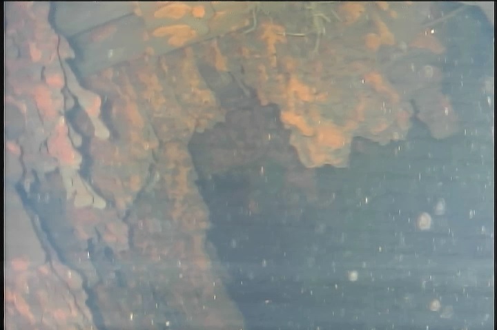
In images #2 & #3 of reference #4, we see what appears to be a flattened pile of granular material. The location of the granular mass is on the periphery of the pedestal, which is the least likely location for a hemispherical bottom head melt-through. We can also see some of the grating that used to be part of the maintenance “carousel” below the CRDMs, leaning against the pedestal wall. But, it is not clumps of material we would surely have if it were corium. The material that consists in the granular mass is currently indeterminate.
On the other hand, image #1 of reference #5 shows a mass comprised of small pieces of something, located under the center of the bottom head. This could be corium that shattered into chunks when hitting the water inside the pedestal and almost-instantly cooled below the melting point of the liquefied material (~2,000oC). Further, the pile is below the central area of the bottom head, precisely where molten corium should be most-likely to gather. Thus, it is likely that most of the small chunks are corium… but not allo of it is.
There is visible damage is to the thick steel clamping brackets located that were firmly attached to the CRDMs. Let’s look at page 1 of reference #3 showing the intact clamps under the unit #5 RPV, for comparison. It appears that many of the unit #3 clamps are gone, and many of those that remain show the evidence of deformation due to overheating. Further, the two “icicles” mentioned in most Japanese Press reports are located below a CRDM housing on the edge of where its support clamp is missing. Are the icicles corium? Or, are they the last vestiges of a support clamp that was being liquefied by the intense heat from the RPV and drizzling-down corium? (More on this later) Thus we should ask how much of the pile of chunky rubble below the center of the RPV is what remains of the missing clamps?
Adding to conundrum, on July 17, Muon imaging of the unit #3 RPV indicated little corium remaining in the RPV proper. (6) The image was compared to the one made with unit #2. The unit #2 image posted last July 28th indicated that some of its damaged fuel (9-23%) remains within the core barrel, and most if not all of the actual corium had collected in the hemispherical bottom head of the RPV. On the other hand, Tepco’s unit #3 image indicates that only a small fraction of the corium remains “in the core and at the lower area of the RPV…” The Tepco handout says, “The evaluation at present shows the possibility that some fuel debris remain(s) inside the RPV, but massive and high density material has not been found.”
There’s not enough of a corium-likely debris pile inside the pedestal, under the unit #3 RPV, to account for where the melted core and attendant materials might be. If it is not inside the bottom head of the RPV, as with unit #2, then where is it?
On July 30th, Tepco announced that the corium from unit #3 probably did not melt through the RPV’s bottom head. The company in effect admitted that the computer-based assumption of a catastrophic “melt-through” now seems unlikely based on the “Little Sunfish” robotic investigation. Tepco now believes that the main mass of the corium collected in the stub tubes that hold the Control Rod Drive Mechanisms. Tepco spokesman Takahiro Kimoto said the images of the RPV underside show that the bottom head itself withstood the heat of molten corium, “We do not presume that the vessel, which is 14 cm thick, melted and collapsed together with the fuel, but that part of the fuel instead made its way down through holes [stub tubes for the CRDMs].” (7)
The CRDMs are not tightly fit inside their stub tubes. There is a small space between the CRDM housings and the inside each of the stub tubes. This prevents damaging the CRDMs during installation and/or maintenance. This space completely encircles each CRDM, like an outer ring. Though quite small – perhaps a centimeter wide – more than 100 of these spaces comprise a not-small volume. Tepco believes that these spaces accumulated much, if not most of the corium not piled inside the pedestal. The company now feels liquefied corium probably seeped out along the periphery of some of the stub tubes, perhaps at the flanges where the CRDMs are connected at the bottom. The seepage would have dripped onto the support bracket array, and liquefied it. Then, the molten material would then have fallen onto the carousel below the CRDMs, weakened it, and allowing it to eventually collapse into the bottom of the pedestal.
While there is no robotic imaging of the underside of the unit #1 RPV, it seems safe to assume that corium exited its RPV in the same fashion as with unit #3. The volume of corium that might have piled up in a rubble bed below the unit #1 RPV should be less than with unit #3 because the core was more than 40% smaller. As for unit #2, it is likely that somewhere between 180 and 210 tons of its corium remains in the original core “barrel” region and bottom head. (1; pg. 7) A maximum of 30 tons could be squeezed in between the spaces between the centrally-located unit #2 CRDMs and their stub tubes, with none of the material “leaking” out and falling to the floor of the pedestal.
As a result of the above, we can now be reasonably sure that none of the bottom heads of the three F. Daiichi RPVs were compromised by the March, 2011 meltdowns. The phrase “catastrophic melt-through” is no longer appropriate.
References –
1 – Locating Fuel Debris inside the Unit 2 reactor using a Muon Measurement Technology at Fukushima Daiichi Nuclear Power Station: Qualitative analysis of substances inside the reactor pressure vessel; page 7 of 9. http://www.tepco.co.jp/en/nu/fukushima-np/handouts/2016/images/handouts_160728_01-e.pdf (unit #2 and unit #3 have the same power-output and dimensional values.)
2 – Buongiorno, Jacopo; BWR Description; Massachusetts Institute of Technology, Fall, 2010. https://ocw.mit.edu/courses/nuclear-engineering/22-06-engineering-of-nuclear-systems-fall-2010/lectures-and-readings/MIT22_06F10_lec06b.pdf
3 - Progress of Unit 3 PCV internal investigation (Preliminary report of July 22 investigation); page 1 of 2, July 22, 2017. http://www.tepco.co.jp/en/nu/fukushima-np/handouts/2017/images/handouts_170722_01-e.pdf
4 - http://photo.tepco.co.jp/en/date/2017/201707-e/170722-01e.html
5 - http://photo.tepco.co.jp/library/170721_01/170721_02.jpg
6 – https://www4.tepco.co.jp/en/nu/fukushima-np/handouts/2017/images/handouts_170727_01-e.pdf